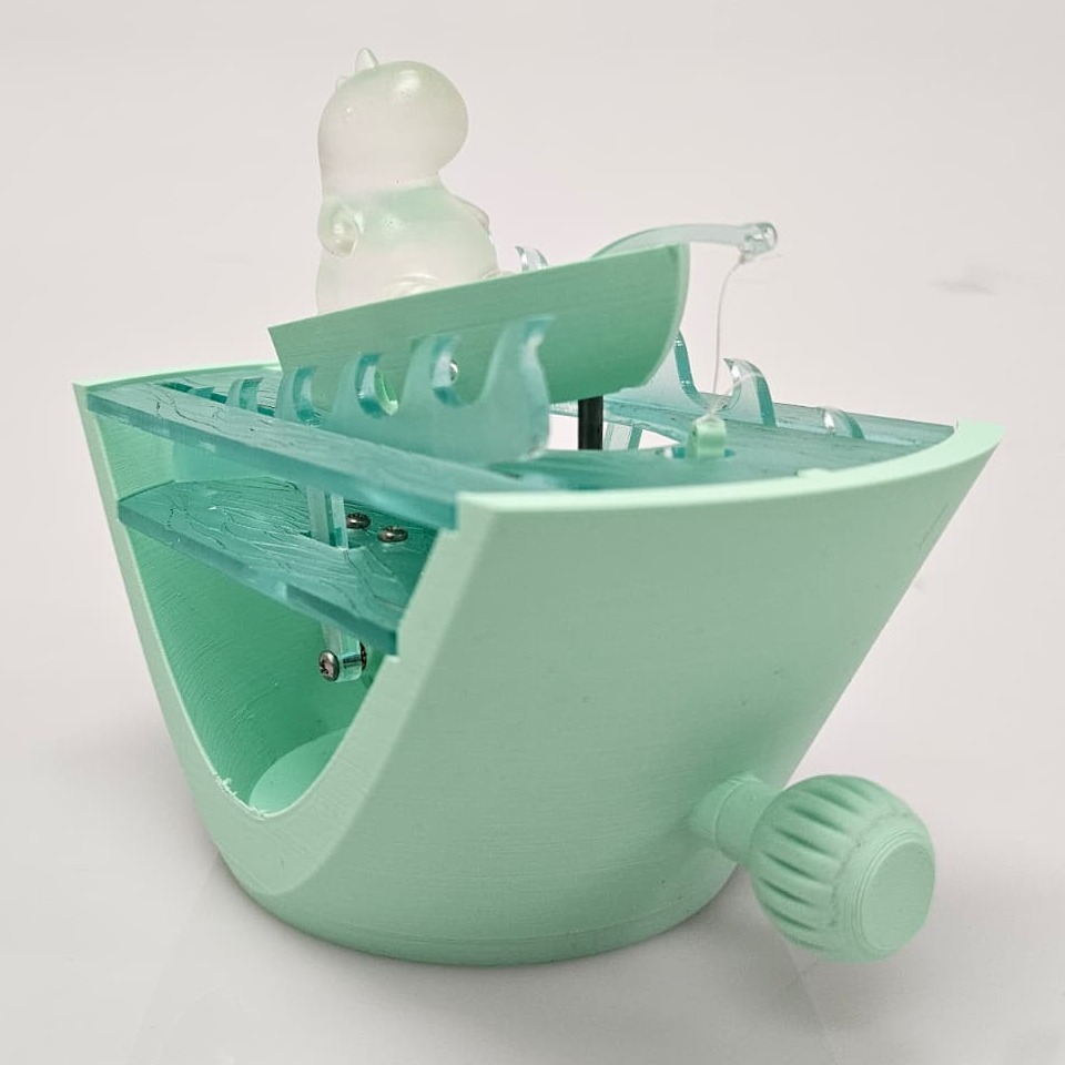
I Think I Can, I Think I Cam: A Dinosaur Story
Who doesn’t love a good dinosaur?
And who doesn’t love the energy of a brave little dinosaur that decides to go fishing only to find out that the fish he caught is a whopper destined for freedom and that his rowboat was going to get caught in a storm?
If you’re still reading, then you agree with me that this is a definitively likeable concept. And sophomore level mechanical engineers need motivation to complete those problem sets in between the coffee and all-nighters. So – of course – I set out to develop our brave little dinosaur and to build him into an automata-style mechanism.
15 months later, and I’m staring at a 3D printed, laser cut, heavily revised but happily fishing dinosaur. It started as a mechanism design prompt focused on achieving rhythmic, continuous motion and creating a representative CAD model. It turned into a prototype that gnawed away at me for almost a year after the final assignment was submitted.
It was meant to be simple. A single manually operated hand crank moves a few components. The rowboat goes up and down smoothly – one wave cycle to one rotation. The fishing pole? Snail cam. Double drop as that fish fights his way to freedom. Just for fun, we’ll add in a crank and waves to showcase the storm that he’s trapped in. We’ll use a 1:1 helical gear just to flip our axis 90 degrees and give a nice challenge for savvy engineering students.
Conceptually, it was that simple. Map your drop distances to your cams. Align your cams at the right angle. Offset your axes on the helical gear along the pitch diameter of the gear. Model a few of these elements into the master CAD model and make sure it all lines up. Small potatoes.
The transition to the physical world was not kind. The first 3D print was impossible to assemble – there was no way to get to the screws. The next print fixed that, only to find out there were screwhead clearance issues. Great, just redesign the brackets. No, the heat set inserts are too long and they stick out. Order smaller ones. Switch to set screws because the smaller screws jam on those redesigned brackets. Allen key is a non-standard size, pay for McMaster shipping. Switched from a bambu printer to a prusa: now my laser cut panels don’t fit right. Add interferences into the model since the bambu under-extrudes filament and that laser cut panel needs to be snug. Main axis is sliding again – and yes, that’s the sound of my followers slipping off the cams and falling to the floor one. More. Time.
It wasn’t just adjusting tolerances. It was creating fixtures for aligning components and creating press fits for square nuts. Thinking about print orientation to avoid supports and how to adjust for laser kerf to make things just a liiiittle bit tighter. Choosing to drill out the holes and get that tolerance perfect rather than getting into arguments with the 3D printing layers.
And in the process you learn.
My CAD model is on version 56 – but if you had only asked the digital model, it was done at version 10. Digital models don’t account for the real world. They don’t account for human hands, screwdrivers, and temperamental 3D printers.
Hardware IS hard. Mechanical design needs finesse. But at the end of the day?
The waves rage, the fish tugs his way to freedom, and our dinosaur keeps the rowboat steady.
(Alright, his fishing pole broke – but I can waterjet that out of aluminum next week… right?)